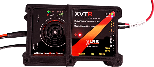
Satpro Digital Video, XVHD
Digital Video, XVHD
Table of Content:
- Default Configuration XVRE y XVTR.
- Installation digital video receiver XVRE in SATPRO.
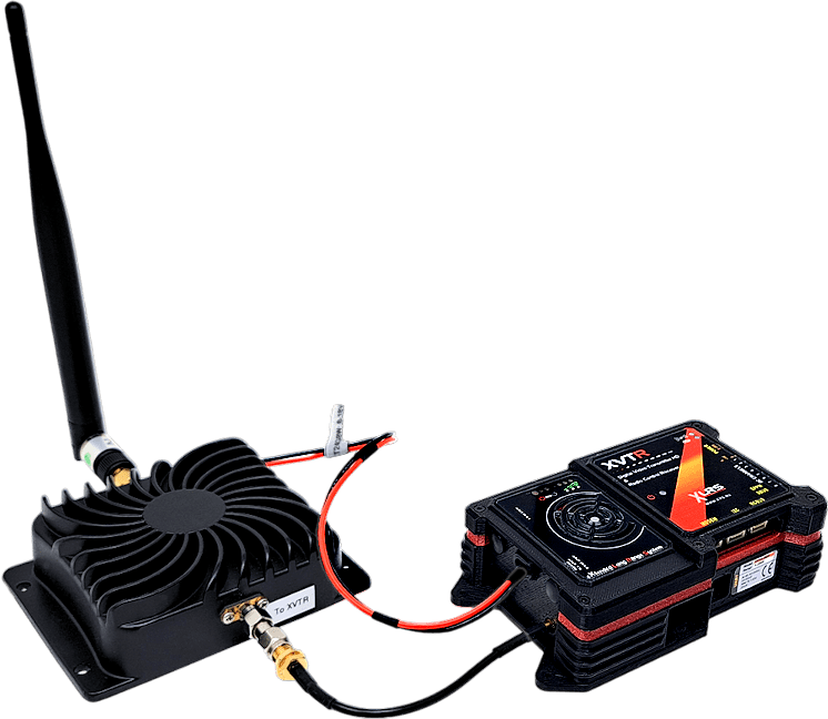
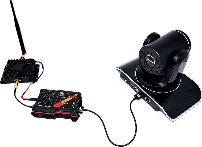
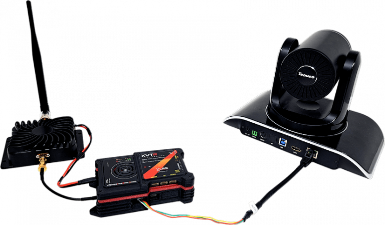
- Connetion, XVTR with XBOOST24G8W and Video Camera.

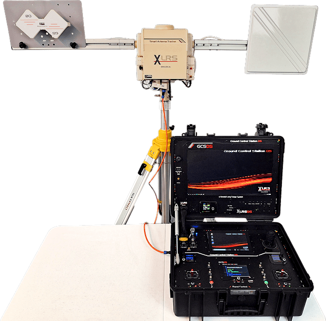
The purpose of this guide is to check the operation of the XVHD digital video system, XVRE digital video receiver that is placed on the side of the SATPRO, the XVTR digital video transmitter and XBOOST24G8W video booster.
You will use: The SATPRO tracker antenna together with XVRE, XVTR, XBOOST24G8W and (XLRS GCS, Monitor TV or a PC connected to the network), you can also have the WMX481 connected to the SATPRO.
Attention:
Default configuration XVRE, Video Receiver (Ground Unit)
IP: 192.168.1.36
Gateway: 192.168.1.1
Ground RTSP Server: rtps://192.168.1.36:554/Stream0
IP Camera Addess: RTPS:// 192.168.1.100:554/Stream0
Default configuration XVTR, Video Transmitter (Air unit)
IP: 192.168.1.100
Gateway: 192.168.1.1
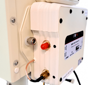
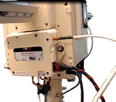
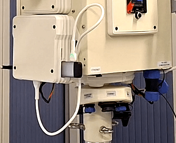
Installation digital video receiver XVRE in SATPROIf you have purchased the XVHD digital video system separately, you will need to install the XVRE video receiver in your SATPRO.
If you have already purchased SATPRO together with the XVHD digital video system, XVRE will already be factory installed on your SATPRO.
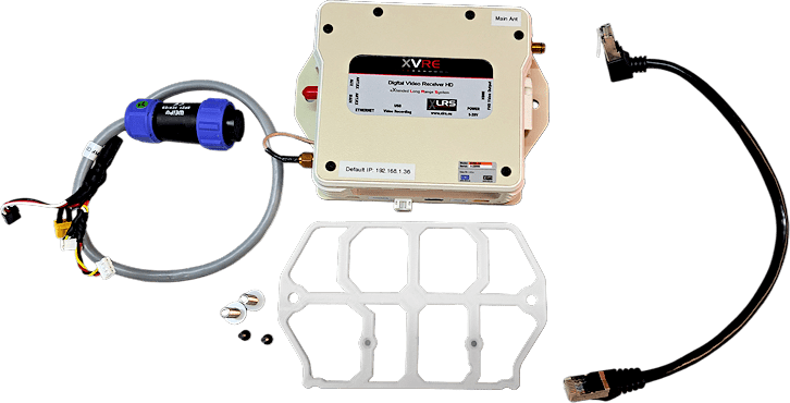
Accessories:
These are the accessories and cables that are included in the XVRE, digital video receiver.
Steps to install and conect XVRE in SATPRO:
1- Take the plastic piece along with the two M3x10 countersunk screws, place them in the two central holes and screw them into the side of SATPRO
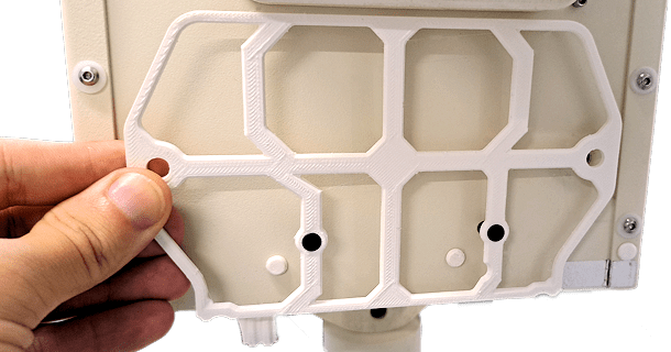
2- Take XVRE and place it on the plastic piece, now take the two M5x20 allen screws along with two M6 Nylon washers and screw them into the holes at the ends of the aluminum piece of the XVRE.
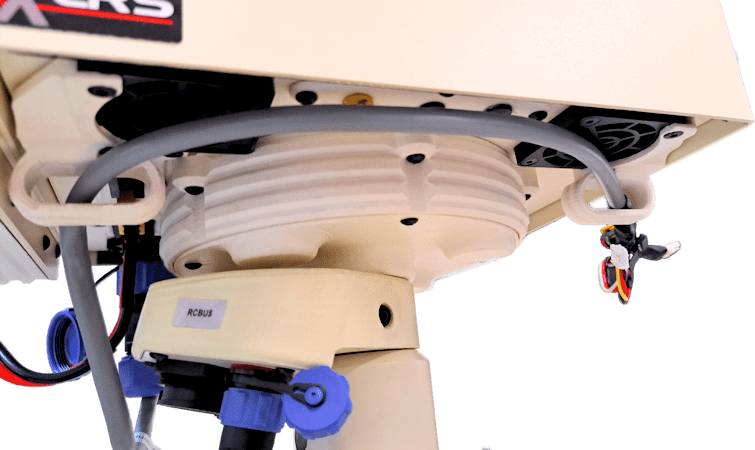
4- Pass the cable through the two plastic guides under the SATPRO until it reaches the XVRE.
Connection, XVTR with XBOOST24G8W and Video Camera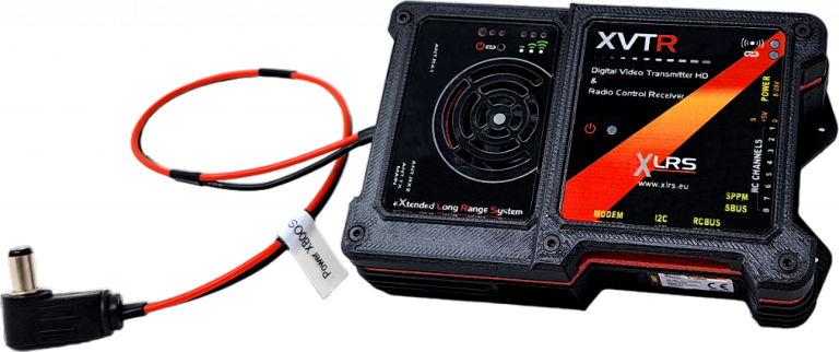
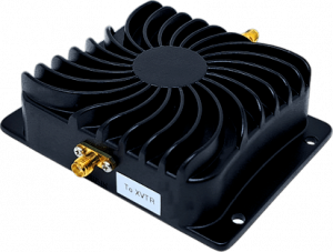
2- On video antenna output from the XBOOST24G8W connect an SMA-Male-RP to SMA-Female adapter and place a 2.4Ghz 5 dBi omnidirectional antenna.
3- From XVTRE connect the power cable to the XBOOST24G8W.
4- Video camera.
4.1- HDMI: Take the HDMI cable, connect it between XVTR and the video camera.
5- Take the power cable for XVTR and plug it into the XT30 Male connector. XVTR power between 8-28V.
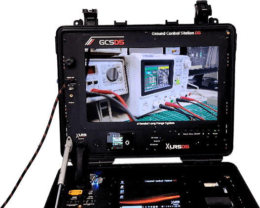
View digital video signal on GCS, TV monitor or similar through HDMI.1- Turn on XVTR + XBOOST24G8W + Gimbal connected by HDMI.
2- Check the XVTR LEDs, at this moment they should be in the following states:
XVTR Power indicator:
Fixed Red Led.
Video Transmitter power indicator:
This indicator is solid green when air unit is booting.
When air unit has started, indicator light blinks once per second if there is no video source input to HDMI.
Link indicator:
Led off, no link (Waiting for link with XVRE).
Status Indicator:
Led off (Waiting for link with XVRE).
RSSI Indicator:
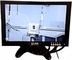
3- In XVRE connect an HDMI cable to the GCS HDMI input or to a TV monitor.
4- Turn on SATPRO together with XVRE and GCS connected by RCBUS.
6- If you are using GCS remember to activate the configuration on the screen to display the HDMI input or if the PC is displayed on the large screen then you have to press the switch button to switch to the video input.
7- Wait a few minutes until XVTR obtains a link with XVRE.
8- Once you are receiving video and have a link, check the status of the LEDs to verify that everything is working well:
XVTR Power indicator:
Fixed red Led.
Video Transmitter power indicator:
Indicator light will be solid green if there is video source.
Link indicator:
Led green on, wireless link with XVRE is established.
Status Indicator:
Led green, blink 3 times Initialization ok.
RSSI Indicator:
3 solid green wireless signal is strongest.
2 solid green wireless signal is medium.
1 solid green wireless signal is weak.
9- If everything is ok, you should see the video from the GCS screen or from your Monitor.
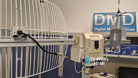
 View digital video signal on GCS, TV monitor or similar through TX & RX 60Ghz Wireless HDMI.In this example we will use the 1080p 60Ghz HDMI TX and RX wireless modules, without delay, to receive the HDMI video signal from the XVRE video receiver without using HDMI cables to a GCS, TV monitor or similar.
Additional Information:
Transmission range 5 meters (LOS).
Steps:
1- Turn on XVTR + XBOOST24G8W + Gimbal connected by HDMI or ethernet.
2- Check the XVTR LEDs, at this moment they should be in the following states:
XVTR Power indicator:
Fixed Red Led.
Video Transmitter power indicator:
This indicator is solid green when air unit is booting.
When air unit has started, indicator light blinks once per second if there is no video source input to HDMI.
Link indicator:
Led off, no link (Waiting for link with XVRE).
Status Indicator:
Led off (Waiting for link with XVRE).
RSSI Indicator:
3- In the XVRE connect the 60Ghz HDMI wireless TX, you can power the TX by connecting a USB cable between the TX and the XVRE.
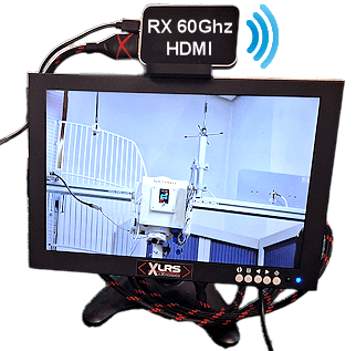
4- In the GCS Monitor, TV Monitor or similar connect the 60Ghz HDMI wireless RX, you can power RX by connecting a USB to a standard mobile phone power supply or directly to a USB port on your PC or similar.
5- Turn on SATPRO together with XVRE and GCS connected by RCBUS.
6- If you are using GCS remember to activate the configuration on the screen to display the HDMI input or if the PC is displayed on the large screen then you have to press the switch button to switch to the video input.
7- Wait a few minutes until XVTR obtains a link with XVRE.
8- Once you are receiving video and have a link, check the status of the LEDs to verify that everything is working well:
XVTR Power indicator:
Fixed red Led.
Video Transmitter power indicator:
Indicator light will be solid green if there is video source.
Link indicator:
Led green on, wireless link with XVRE is established.
Status Indicator:
Led green, blink 3 times Initialization ok.
RSSI Indicator:
3 solid green wireless signal is strongest.
2 solid green wireless signal is medium.
1 solid green wireless signal is weak.
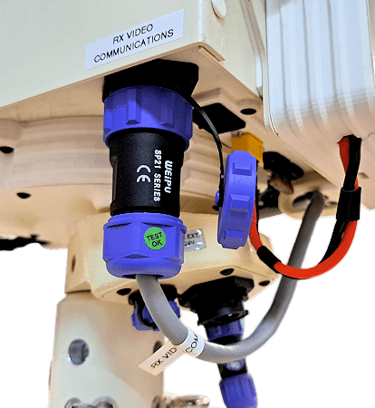
9- Check the link of the TX and RX 60Ghz wireless HDMI.
States of signal indicator:
Red: Power On.
Blue: Searching Signal.
Green: Pair and Connect Successful.
Reset button:
Method: Press and hold the reset button of the TX and RX for 10 seconds simultaneously. After the indicator is off, release reset button, and the device will establish the connection.
10- If everything is ok, you should see the video from the GCS screen, TV Monitor or similar, range max 5meters (LOS).
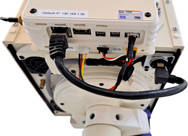
View digital video signal on GCS PC, external PC or similar device through ethernet network.IP default configuration:
XVTR IP: 192.168.1.100
XVRE IP: 192.168.1.36
Gimbal IP: 192.168.1.102
Important:
The IP configuration of the Gimbal must be on the same network as the XVTR and XVRE.
Steps:
1- Turn on XVTR + XBOOST24G8W + Gimbal connected by ethernet.
2- Check the XVTR LEDs, at this moment they should be in the following states:
XVTR Power indicator:
Fixed Red Led.
Video Transmitter power indicator:
This indicator is solid green when air unit is booting.
When air unit has started, indicator light blinks once per second if there is no video source input to HDMI.
Link indicator:
Led off, no link (Waiting for link with XVRE).
Status Indicator:
Led off (Waiting for link with XVRE).
RSSI Indicator:
3- In XVRE connect the Ethernet cable from XVRE to SATPRO (Use the short Ethernet cable that comes in the SATPRO case).
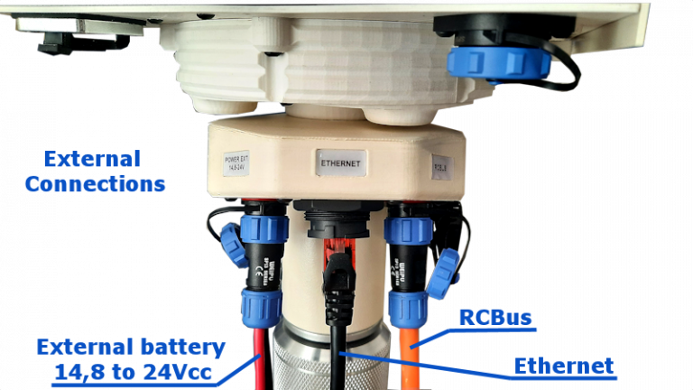
4- From the SATPRO external connections, we connect an ethernet cable from SATPRO to the network.
5- Connect GCS PC, external PC or similar device to the network.
7- Wait a few minutes until XVTR obtains a link with XVRE.
8- Once you are receiving video and have a link, check the status of the LEDs to verify that everything is working well:
XVTR Power indicator:
Fixed red Led.
Video Transmitter power indicator:
Indicator light will be solid green if there is video source.
Link indicator:
Led green on, wireless link with XVRE is established.
Status Indicator:
Led green, blink 3 times Initialization ok.
RSSI Indicator:
3 solid green wireless signal is strongest.
2 solid green wireless signal is medium.
1 solid green wireless signal is weak.
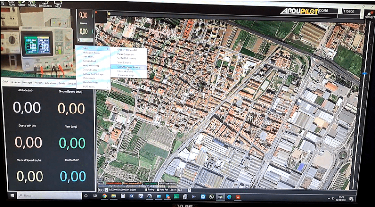
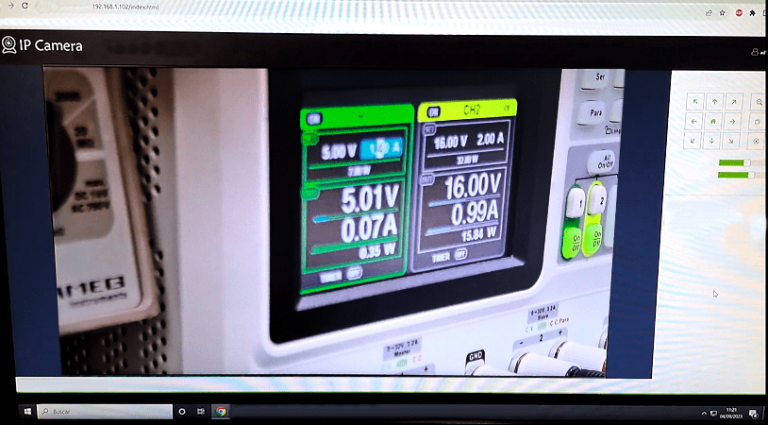
9- From the web browser or from your software, access your gimbal, add the IP of the Gimbal in this case by default it is configured at IP: 192.168.1.102 and establishes communication.
10- If you want see the gimbal video signal from Mission Planner or similar software, then we open MP, on the main page in the HUB we right click, select Video/Set GSTreamer Source and input the address: rtspsrc location=rtsp://192.168.1.36/stream0 latency=0 ! decodebin ! videoconvert ! video/x-raw,format=BGRA ! appsink name=outsink, press OK and would show the video integrated into the map.